Schematic Overview
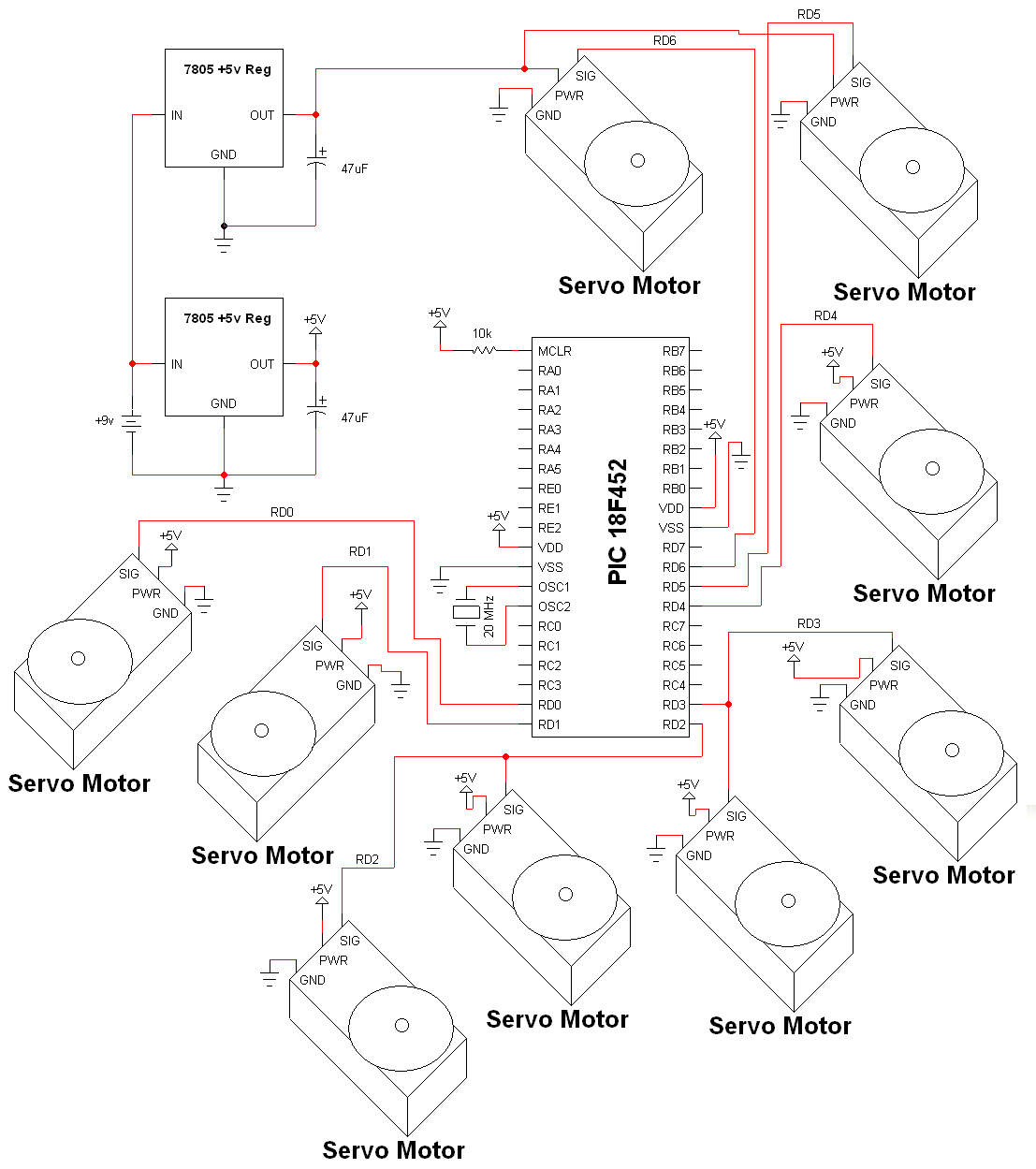
The electrical schematic for controlling the servo motors that we're using as acuators is surprisingly simple due to the fact that the servos are very self contained. The PIC will control them with a specific signal for each servo. The main devices used in the circuit are the HS-485HB, HS-645MG , 7805 and PIC 18F452.
View Full Schematic
Schematic Specifics
Power Circuit
Two 7805 power regulation circuits are used to power all of the servos and the 18F452. The reason I use two of these circuits is simply because one 7805 would not be able to supply enough power when all of the servos are at full-load.
Microcontroller Circuit
The PIC circuit consists of the 20 MHz crystal, some connections to power and ground and a 10kΩ resistor pulling pin 1 up to +5v. PORTD's RD0 and RD1 will be used to send control signals to the servo motors.
Servo Circuit
With this final design there are a total of 9 servo motors being controlled by the PIC. Please notice that RD2 and RD3 control signals each go to two servos. That is because I decided independent eye control wouldn't be necessary anymore. You could definitely assign a single I/O port to each of these servos if you wanted, however in the long run my way is easier =D.