Hardware Design
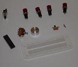
First things first we need to gather all the parts we're going to use. Below are a few pictures of the initial parts we're going to use. Breadboard wire & Wire wrap are not pictured but they'll be just as necessary for wiring everything up.
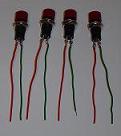
The first step towards putting together the VGA Test Box begins with the buttons. With a Soldering Iron, some solder & AWG 24 wire we solder the wire onto both pins sticking out of the buttons. Luckily each of the metal pins sticking out of the button has a hole in it that the wire fits nicely through & can be soldered onto solidly. Make sure the wire can't be moved and is firmly attached to each pin off of the buttons. Click on the middle picture above for a closer look.
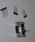
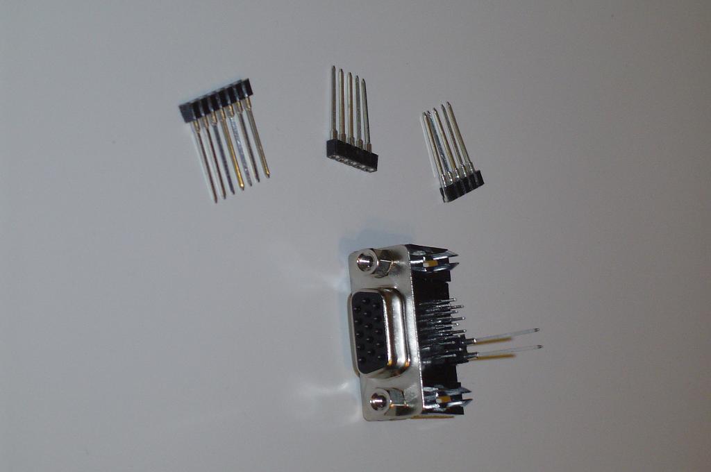
Now we want to put SIPS onto the VGA connector so that we can wire wrap easily onto the connecter and connect to the PIC microcontroller. An example of this is seen in the 3rd picture above. Remeber that we're only interested in pins 1,2,3,10,13 & 14 and so only 6 SIPS are necessary. Refer back to page 1 of the Theory of Operation for VGA connector pinouts. It is imperative that you correctly identify the pins. If you wire up the wrong pins, the project will not work properly.
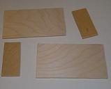
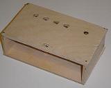
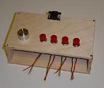
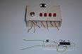
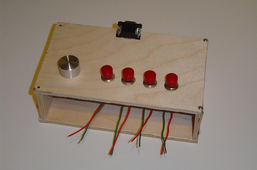
The next step is to get some hobby wood and cut the shapes so you can make a nice little box. With a power drill, drill 4 holes for the buttons, 1 hole for the SPTT switch, 1 for the VGA connector & a small one for the on/off SPDT switch. Click any of the pictures above for more detail. The buttons & switches were all super-glued in to secure them. Please note that I am by no means a professonal carpenter. I just use the tools that I have available to me.
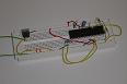
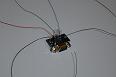
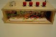
The final step is putting everything together. I started with assembling the schematic on the breadboard. The first picture above shows that nicely. Next I used different color wire wrap off of the VGA connector. The other end of the wire wrap will wrap nicely onto the loose wires you see sticking out of the breadboard & off of the SPTT switch (for R/G/B). The last picture shows everything put together and hooked up. So now the only thing left to do is program the PIC microcontroller & then it will work!
First things first we need to gather all the parts we're going to use. Below are a few pictures of the initial parts we're going to use. Breadboard wire & Wire wrap are not pictured but they'll be just as necessary for wiring everything up.

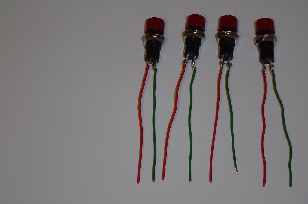
The first step towards putting together the VGA Test Box begins with the buttons. With a Soldering Iron, some solder & AWG 24 wire we solder the wire onto both pins sticking out of the buttons. Luckily each of the metal pins sticking out of the button has a hole in it that the wire fits nicely through & can be soldered onto solidly. Make sure the wire can't be moved and is firmly attached to each pin off of the buttons. Click on the middle picture above for a closer look.
Now we want to put SIPS onto the VGA connector so that we can wire wrap easily onto the connecter and connect to the PIC microcontroller. An example of this is seen in the 3rd picture above. Remeber that we're only interested in pins 1,2,3,10,13 & 14 and so only 6 SIPS are necessary. Refer back to page 1 of the Theory of Operation for VGA connector pinouts. It is imperative that you correctly identify the pins. If you wire up the wrong pins, the project will not work properly.


The next step is to get some hobby wood and cut the shapes so you can make a nice little box. With a power drill, drill 4 holes for the buttons, 1 hole for the SPTT switch, 1 for the VGA connector & a small one for the on/off SPDT switch. Click any of the pictures above for more detail. The buttons & switches were all super-glued in to secure them. Please note that I am by no means a professonal carpenter. I just use the tools that I have available to me.


The final step is putting everything together. I started with assembling the schematic on the breadboard. The first picture above shows that nicely. Next I used different color wire wrap off of the VGA connector. The other end of the wire wrap will wrap nicely onto the loose wires you see sticking out of the breadboard & off of the SPTT switch (for R/G/B). The last picture shows everything put together and hooked up. So now the only thing left to do is program the PIC microcontroller & then it will work!