VGA Monitor
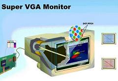

In order to display anything on the CRT monitor we must first understand how it works. So here it goes. A CRT monitor generally plugs nicely into any generic video card for a computer. The video card, depending on how well it is made often supports several different screen resolutions and frequencies.
Standard VGA Plug Pinout
The standard VGA cable is a DB-15 connector. That means it has 15 pins to communicate with the videocard. Luckily for our project, not all of the pins will need to be used. Pins 1, 2, 3, 10, 13 & 14. Will be used. If you take a quick look back at the schematic You can see we only have 6 pins hookig up to the CRT.
VGA Monitor
-
Pin 1 - Red
This pin controls the intesity of Red displayed at the current point on the monitor. -
-
Pin 2 - Green
This pin controls the intesity of Green displayed at the current point on the monitor. -
-
Pin 3 - Blue
This pin controls the intesity of Green displayed at the current point on the monitor. -
-
Pin 10 - Signal Ground
Signal Ground defines the ground for the signal pins. This serves us as a common ground as it is connected to all other ground pins. Since we use 1 power source, we need only use 1 ground pin. -
-
Pin 13 - Horizontal Sync
This pin is used to tell the monitor when data is finished being transmitted onto the current line of the screen. -
-
Pin 14 - Vertical Sync
This pin is used to tell the monitor when data is finished being transmitted onto the current field of the screen & to move onto the next screen.